Background
I took part in a research endeavor to analyze many facets of guided/autonomous parachutes this last 3 months. There are many technical problems that require solutions for this project to be successful and the following analysis presented below is the culmination of 3 months of research dedicated to airframe system identification and proof of closed loop autonomy. This project was comprised of two teams working in parallel. The other team worked on increasing the parachute deployment reliability as well as manual control of a parachute. Because our team was responsible for solely creating a model from logged flight data and proving low-level autonomy, it was chosen to use a reliable fixed wing airframe instead of the parachutes to more effectively solve the system’s problems without potentially being hindered by airframe reliability. Proving our methods of analyzing the system on the fixed wing aircraft can easily be modified to the parachute airframe once it comes online.
1: Pixhawk Autopilot
2: 3DR Ublox GPS and magnetometer unit
3: 3DR 900 Mhz wireless telemetry modem suit
4: 350mAh Lithium battery (2 cell)
5: 3 Amp / 5v Battery Eliminator circuit (Hobby King generic)
6: 3 x 5gram servos (Hobby King Generic)
7: Dollar Tree Foam board (1 sheet per aircraft)
8: Hot glue gun / hot glue sticks
9: Custom 3D printed parts for release mechanism (described below)
10: Ultimaker 2 3D printer
11: Laser cutter
The first part of our project was to design the airframe. A small wingspan was desired to fit below the Arcturus UAV to ensure minimum interference. We also didn’t want the high glide ratio of a glider, because we were aiming for flight characteristics similar to that of a parachute. The design chosen was a delta wing plan-form with a very low aspect ratio. The flying wing architecture is easier to build, is compact, and uses the least amount of servos for stabilizing flight. This design did not utilize a motor. It may be familiar to some of you as a version of the Punjet found at:
The Fuselage was widened to accommodate the Pixhawk and tapered in the back. The wingspan was also increased by the same thickness added as the fuselage. The first step in designing the aircraft, was to design the fuselage such that it could carry the autopilot. The physical dimensions of the Pixhawk autopilot were what dimensioned the fuselage. Essentially the whole aircraft was designed around the autopilot. The second design constraint was the release mechanism. The aircraft had to be able to release itself from the Arcturus UAV with it own servo release mechanism. The space required to house the release mechanism was a concern. However, shaping the fuselage around the autopilot gave ample room for the release mechanism as well as the telemetry modem, gps and battery.
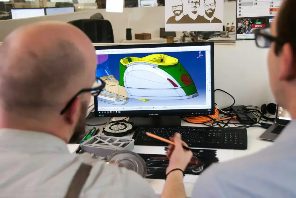
The plans illustrated below were generated in Inkscape (open source version of CorelDraw) from the modified flitetest pdf vectors.
These plans were plotted on paper to lay out the electronics and do one last test fit to ensure scaling and servo cutouts were correct. The Inkscape final plans file was converted to a vector file (generic SVG in Inkscape) in order to be printed on a laser cutter. The black lines represent a cut that is all the way through the foam board, and the red lines represent a half score cut through the foam board. The print settings for the laser cutter let you set the laser’s power and speed relative to the color. Using scrap foam board, test cuts at different power levels and speeds were tested to get the desired performance per the respective color. The final power/speed settings used for accurate cutting were as follows:
Black: Speed=20%, Power=100%
Red: Speed=20%, Power=55%
It was also found that using the flattest foam board possible ensured the most accurate cuts. It was also very important to run the auto-focusing procedure for the laser every time cut was performed.
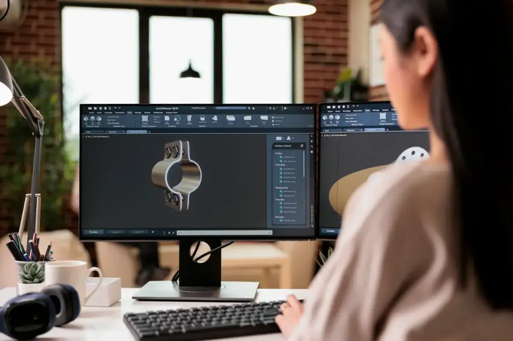
The next part of the design process was to design the release mechanism. The release mechanism comprises to two primary parts: the base plate designed to spread the launch forces across the bottom of the aircraft and the hook capture device designed to capture the wire. These two parts were drawn in 3D CAD (Solid Works) and then printed on an Ultimaker 2 3D printer. These results can be seen belowThe next part of the design process was to design the release mechanism. The release mechanism comprises to two primary parts: the base plate designed to spread the launch forces across the bottom of the aircraft and the hook capture device designed to capture the wire. These two parts were drawn in 3D CAD (Solid Works) and then printed on an Ultimaker 2 3D printer. These results can be seen below:
The Pixhawk was configured with the ‘plane’ software and stock PID settings were used for the initial flight. The elevon settings, correct command orientation, as well as PID attitude feedback were all verified as correct. The servos were reversed on the ground station until the correct behaviors were observed. Channel 7 was used for servo pass through to actuate the release hook servo.
The transmitter mode switch was capable of selecting 3 flight modes on the autopilot. These three flight modes were chosen in a progressive nature to ensure safe flight through the multi-flight test flight process. For example, the first flight was setup with the following: 1: manual, 2: Auto tune, 3: Fly By Wire A. This was to ensure that if the attitude PID gains were too high, the flight mode could be selected for manual control. Return to launch and/or orbit was not selected for any of the 3 modes for the first flight because the underlying attitude controllers needed to be proven.
On the first flight, it was intended to utilize the auto-tune algorithm for attitude control to further refine the PIDs. The attitude PIDs recorded from the first short flight were not that much different from the stock PIDs. The primary influencing gain of focus for these first flights were the proportional gains. The stock value for these gains was 0.4 ( a fairly conservative value). The short flight time only enabled the P_roll to increase to 0.43.
The aircraft was tested for release and physical interference with the Arcturus UAV. The release mechanism successfully released multiple times on the ground and did not interfere with the Arcturus UAV. All subsequent flights all had 100% successful drops.


